This page is about the robot my team and I built and programmed for the Engineering Education Scheme that I applied to take part in while doing my first year of Sixth Form College in 2017-18. The task we were given from QinetiQ was to design and build a concept robot that would navigate through dangerous building or terrain that people couldn't do safely that could be used to deliver payloads or for search and rescue and things like that. This page will only be going through the fun bits of the project, I won't be writing about any of the boring report sections we had to write, like the success criteria or evaluation bits, it'll just be the fun stuff, don't worry.
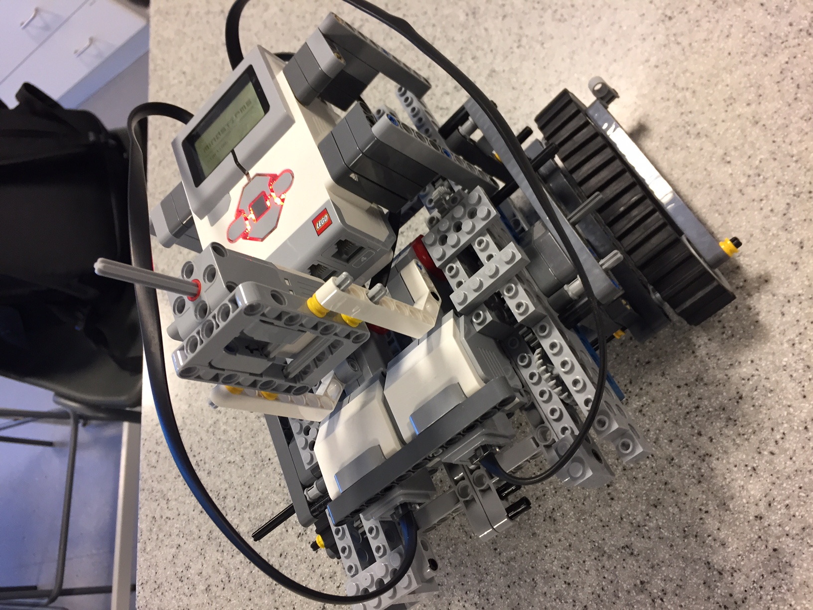 |
At the start, we got given a huge box of Lego technic and mindstorms stuff, so before we decided on or bought any of the parts we needed for our final robot, we made a lego concept. We also didnt have the right kind of tracks we wanted, which is why had multiple gears going down the track legs to give it some ground clearance. |
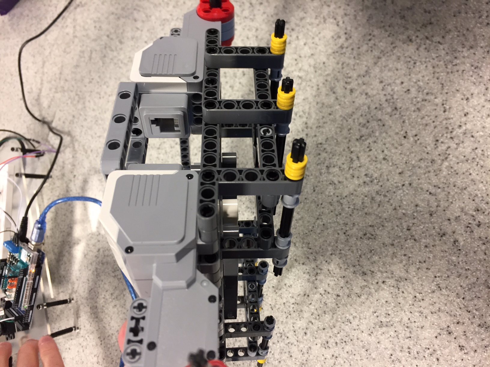
As the gearing system of the concept was just bad and gave the motors too much friction and pressure to work properly, we redesigned the track frame to use two motors per side and the plastic, clip-together Lego treads. We also used a lot of Lego technic parts to join the tread frames together and provide support as a whole chassis. |
 |
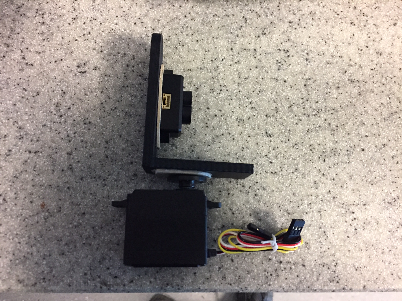 |
We 3D printed a bracket to mount the sensor to a servo which allows the sensor to turn which I use later to make the robot figure out the fastest way to get around an obstacle. The sensor in this picture is a Lidar sensor, but we swapped it out last minute to an ultrasound sensor as I was having trouble getting the Lidar to work reliably in the code. |
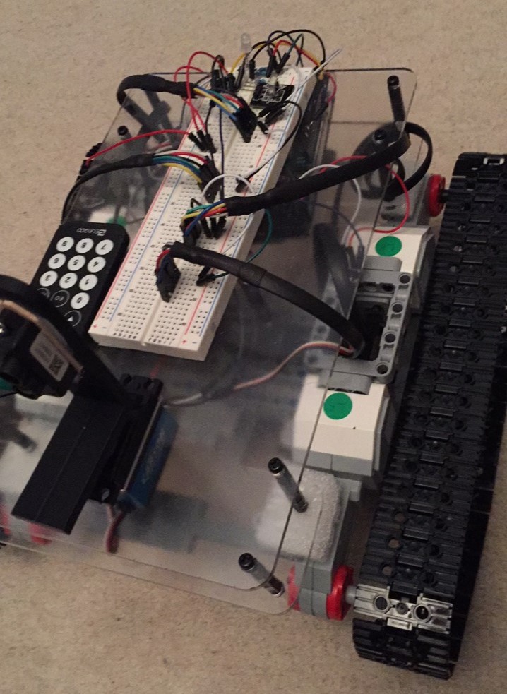
We had a double layered body so we could fit the arduino on the lower platform and the breadboard on the upper one. At the back of the breadboard I also added an IR reciever to enable control from the little remote and an LED to change color depending on which mode the robot was in, self-navigating or manual contol. You can also see the plastic tracks we used, which were infinetly better and didn't put any stress on the motors. |
 |
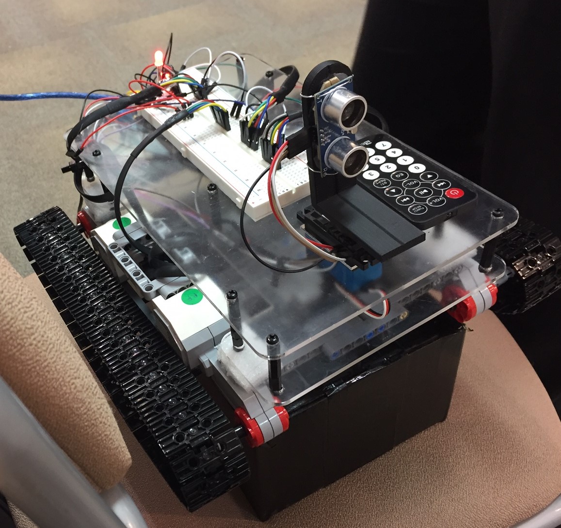 |
This picture is from the EES event at the end of the project, the robot ended up working really well when we tested it a few days before, but it all fell apart on the day due to unreliable wiring connections and the left track stopped working. Overall it was a really fun project and I'd do a lot of things differently if I built something similar again. I'd probably lower the sensor so that lower obstacles can be detected, and I'd probably add a camera for better remote control of the robot. |
I think I've lost the code for the robot so I will have to try and remember what I did in 2017 and explain how I think I programmed it. I may update this if I find the code, but this explanation is probably good enough for this website.
As the tracks of the robot are powered with two motors per side in opposite directions, I made seperate functions per track to go forwards or backwards as I needed both motors of a track to turn simultaneously and in the same direction which means opposite directions in the code. Also as we had no gyroscope or other ways to figure out which way the robot was facing, I think I ended up timing how long it takes for the robot to turn 90 degrees on the spot and using that time to make functions that would get the robot to turn each way. I think I added 45 degree functions as well for more turning precision.
Adding manual control was as simple as mapping certain inputs from the IR sensor when a button is pressed on the remote to toggle actions such as drive forward, turn left, and turn right, and the same button press will stop those actions, so you can turn more accurately than just 90 degrees. I also used a button to toggle modes, so all the manual control code and self driving code were put into different parts of an if-else statement checking what mode the robot is in, which was shown by the colour of the rgb LED.
Originally we planned to be able to give it a destination with coordinates relative to its current postition and it would navigate there itself, but we didn't have enough time, plus our only way of measuring when the robot moved a meter was to time it, which would have been pretty innacurate, as it would change with surface type and angle. Instead, we added object avoidance, so whenever the sensor detected an object within a certain distance, the robot would stop and decide the shortest way around the object by rotating the sensor each way to find the edges of the object, then do some pythagoras to figure out how far it would need to drive to clear the object in the shortest way, and drive around it. It worked pretty well, the only problem being that there was a minimum height required, and it would crash into anything that isn't directly in front of the sensor.